
Explore the most effective techniques for seamlessly blending 3D models into live‑action footage.
In contemporary filmmaking, creatures, elves, and superheroes are often rendered in 3D and composited onto real‑world footage. The success of such shots hinges on meticulous post‑production work that matches color, lighting, and camera motion.
Post‑production is only the final link in a chain of steps that set the project for success:
- Detailed video clip analysis, including micro‑activity breakdown. Imported clips may receive color correction or lens distortion calibration before tracking.
- Exporting the clip to a dedicated tracking application. In this series, we focus on PFTrack by The Pixel Farm.
- Building the final scene in a 3‑D package such as Maya, informed by the PFTrack data.
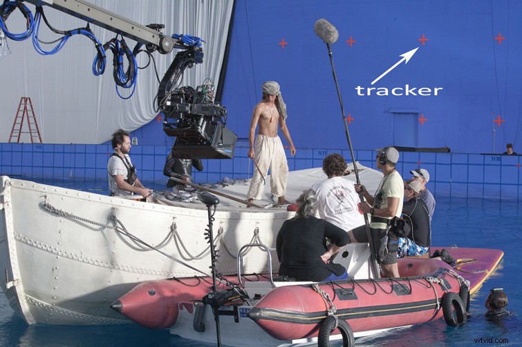 The tank shoot from Life of Pi. Image via fxguide.com
In the image above, the filmmakers captured a real sequence and composited it over a digital background. A blue screen was used, but the prominent red crosses represent tracking markers.
What role do these markers play?
Why Use Tracking Markers?
Tracking markers serve as reference points for the physical camera during shooting. While static scenes may not require them, they become essential for shots that involve camera movement.
The goal is to record the real camera’s motion and transfer it to a virtual camera—what the industry calls camera tracking or match‑moving.
Camera tracking is crucial in two primary scenarios:
- Real actors on set with a CGI background, as in the Life of Pi example.
- Real environments with digital props added in post‑production.
Without accurate camera tracking, integrating live‑action footage with 3‑D renders would produce obvious mismatches.
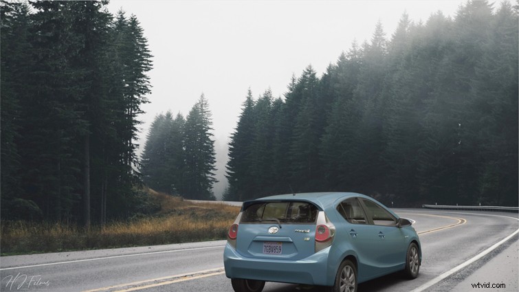 A CG car integrated into a real environment. Image via Personal Project.
PFTrack for Camera Tracking
While many NLEs, such as After Effects, include basic tracking tools, PFTrack is a dedicated solution widely adopted in professional VFX pipelines.
Below is a snapshot of PFTrack after loading a scene.
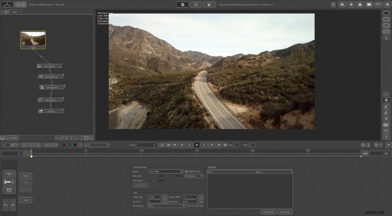 The main PFTrack interface
PFTrack’s node‑based workflow keeps the pipeline organized. The left panel lists active nodes, the center displays the footage and timeline, and the bottom panel shows node‑specific controls.
A Feature‑Rich Tool
For a full reference, consult PFTrack’s official documentation here. The node panel is grouped into functional tabs:
- Tracking
- Solving
- Distortion
- Geometry
- Photo
- Z‑Depth
- Spherical
- Stereo
- Export
- Utilities
- Python
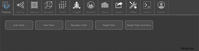 Node Panel in PFTrack
Key categories:
- Tracking extracts features from the clip. Users can choose automatic tracking or manually place custom points.
- Solving builds the virtual camera’s motion from the tracked features.
- Distortion corrects lens artifacts such as barrel or pincushion distortion.
- Geometry lets you insert test objects to validate tracking accuracy.
- Export outputs camera data to Maya, 3DS Max, After Effects, etc.
- Utilities include “Estimate Focal” for correcting focal‑length inaccuracies and “Orient Scene” for aligning the coordinate system.
First Steps
We’ll use a clip from the Shutterstock library here. Import it into PFTrack as an image sequence and start the tracking process.
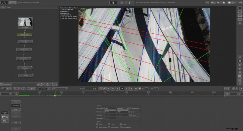
PFTrack’s advanced algorithms usually estimate the correct focal length automatically. If you need finer control, the Estimate Focal node can refine the perspective by manually specifying vanishing points.
In some cases—such as shots taken from above—providing all three axes (X, Y, Z) gives PFTrack the necessary data.
 A project I made by using camera tracking. Image via Personal Project.
Auto vs. User Tracking
PFTrack offers both Auto and User Track nodes. The former automatically identifies stable features; the latter lets you manually place trackers for critical areas.
Guidelines for manual placement:
- Choose high‑contrast regions (e.g., dark pixels against bright backgrounds).
- Place physical markers on set where you intend to insert 3‑D elements.
- Adjust brightness and contrast within PFTrack to make features more prominent.
In our example, we added 12–17 user trackers along the pavement, wall, and other strategic locations.
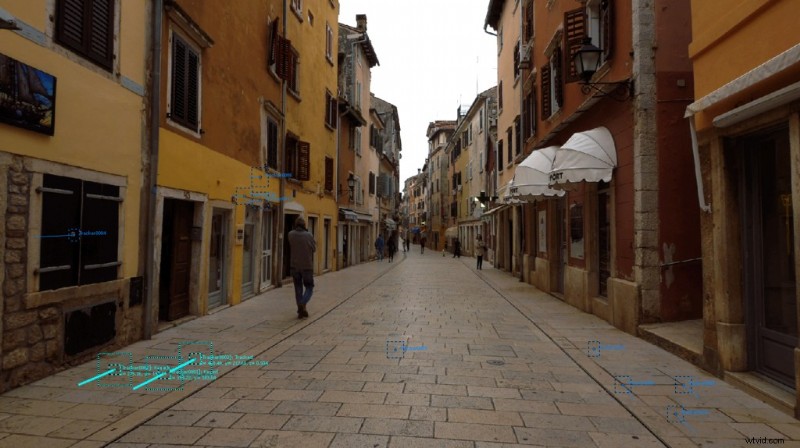 User trackers in strategic areas. Observe their position
Camera Solving
With features established, the Camera Solver node estimates the virtual camera’s motion. Use the “Solve All” action to perform the calculation.
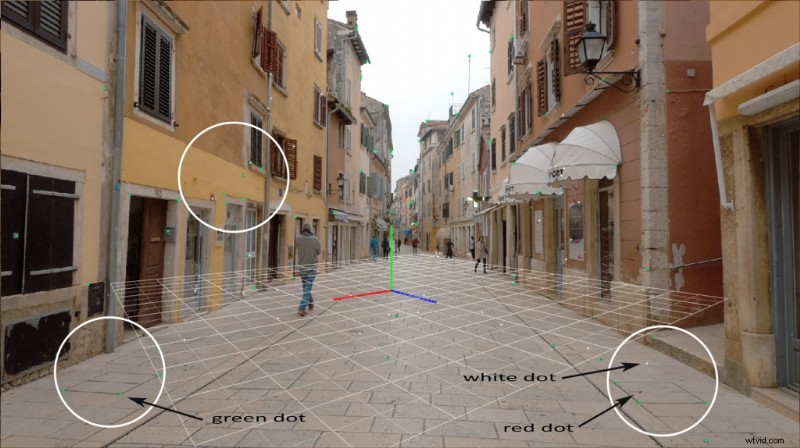 Camera solving with the final points
The solver’s output uses color coding:
- Green – successful projection.
- White – inactive projection for the current frame.
- Red – failed projection (error > 2 px).
- Orange – moderate error (1–2 px).
To improve accuracy, examine the Error Graph. Trim high‑error peaks with the trim tool, stabilizing the average error line toward zero.
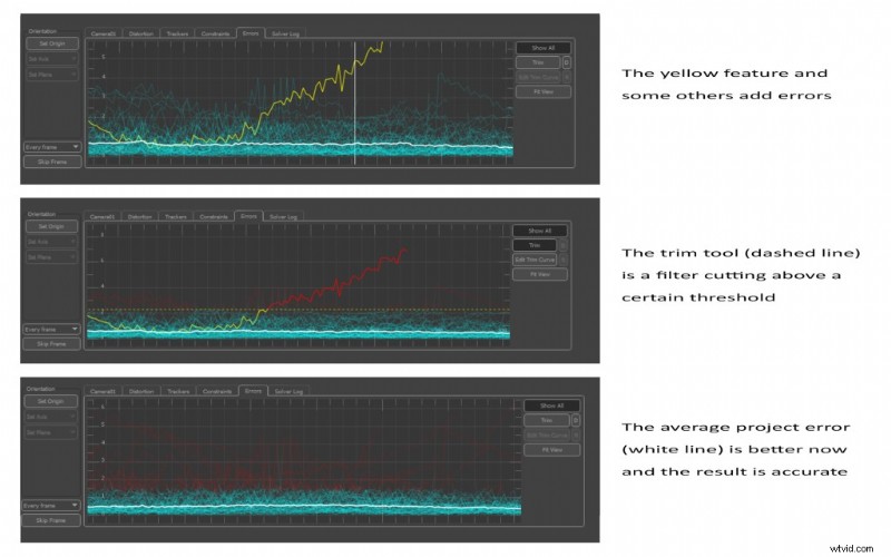
If a tracker consistently performs poorly, deactivate it in the “Trackers” tab and re‑solve.
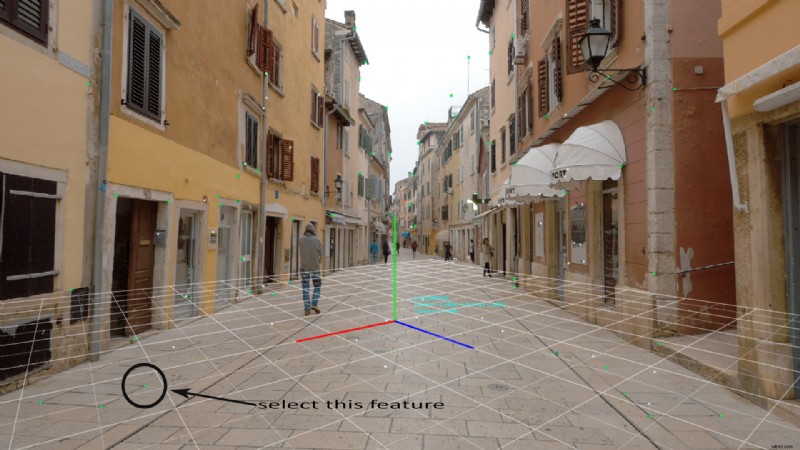
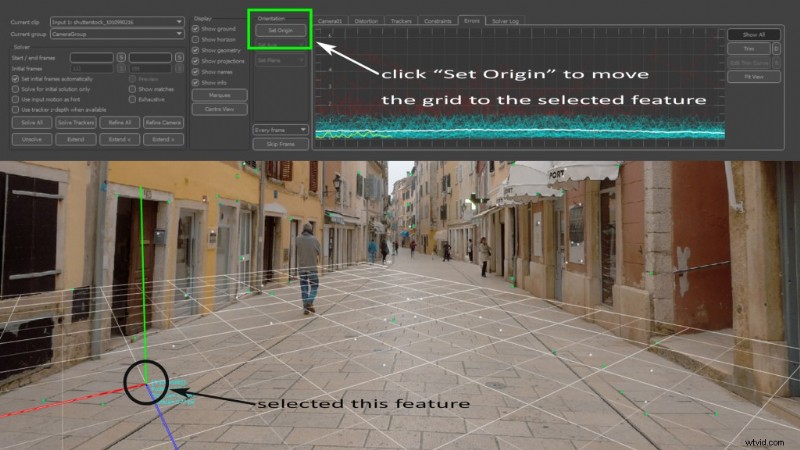
To set a new origin, select a green tracker, then click “Set Origin” in the Camera Solver node.
Orienting the Scene
With a reliable origin, the Orient Scene node aligns the 3‑D grid to match the real world.
Choose three accurate trackers on a flat surface (e.g., pavement) and set them to the X‑Z plane. Adjust the grid’s vertical orientation so that it lies flush with the surface.
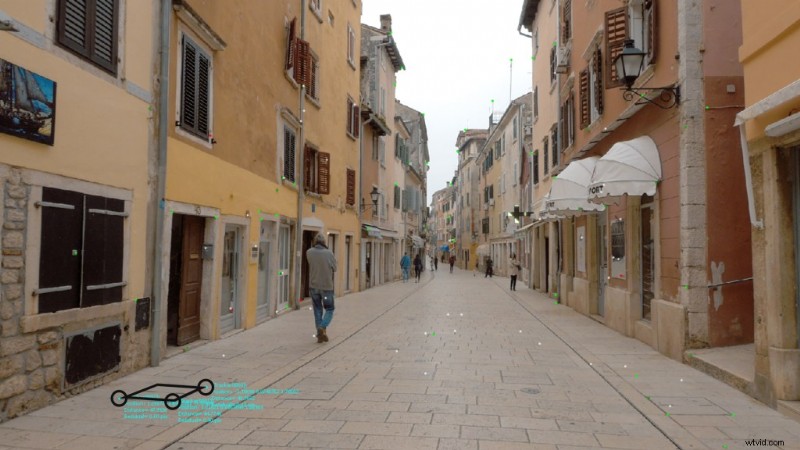
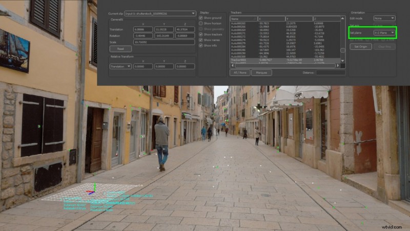 Establishing the right scene orientation
Testing Objects
Once the grid is correctly oriented, import simple 3‑D models using the Test Object node to validate tracking quality.
For precise placement, snap objects to the calculated 3‑D points. When dealing with varying elevations—such as a doorstep—add trackers on corner points, build a rough parallelepiped, and position the object on its top face.
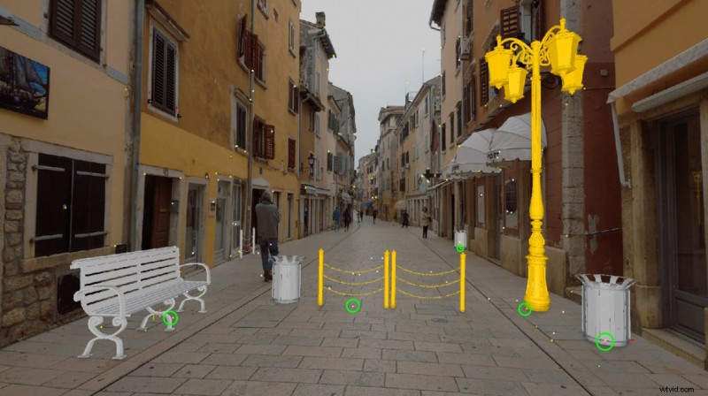 A few 3D objects to test the tracking quality.
Playback the entire sequence to confirm consistency. This test phase excludes lighting, textures, or shadows, focusing solely on positional accuracy.
From PFTrack to Maya
The final step in PFTrack is exporting. Use the Export node to generate camera and scene data in a format compatible with your 3‑D package. For this tutorial, we export to Autodesk Maya.
When you open the exported scene in Maya, the camera animation is already baked, and your 3‑D objects maintain their positions relative to the live‑action footage.
At this point, you’re ready to apply textures, lighting, and render your scene for final compositing.
This concludes Part I of our series. You now know how to use camera tracking to integrate 3‑D meshes into real footage.
In the next installment, we’ll cover:
- Animating 3‑D objects within a video clip.
- Realistic 3‑D lighting and rendering techniques.
- Tips for achieving seamless integration between 3‑D and live‑action footage.
If you enjoyed this article, follow me on LinkedIn for more insights.
New to 3‑D asset creation? Check out these related articles:
- Creating an ACES Workflow for Realistic Lighting with 3‑D
- Improve Render Quality with Layer Composition in After Effects
- From Call of Duty Fan Edits to Music Videos for Russ: An Interview with 3‑D Artist Vollut
- Unlock the Power of 3‑D in After Effects with Helium
- How to Create Real 3‑D Terrain in Blender (Without Plugins)